The
Timekeeper
A room that only lights
when something real
passes through it
A cloud chamber makes invisible particles briefly visible as thin lines of condensation. The Timekeeper enlarges that box onto three surfaces in a dark room — the chamber itself, what the machine extracted from it, and what is left as it fades — each running about a second behind the particle that caused it.
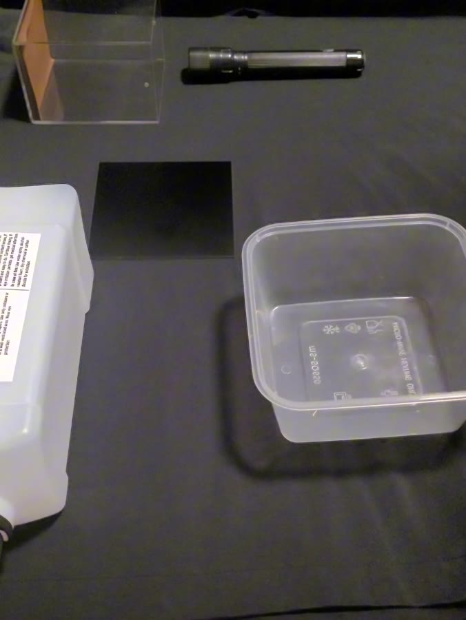
A diffusion cloud chamber, assembled from hardware-store parts. A sealed acrylic box; a felt strip at the top soaked in 99% isopropanol; underneath, a black anodised plate held at roughly −78 °C by dry ice.
The alcohol evaporates warm at the top, sinks, and meets the cold plate. In the few centimetres just above that plate it forms a layer of supersaturated vapour — vapour holding more alcohol than it should be able to, waiting for an excuse to condense.
Anything that ionises the air inside that layer provides the excuse. Droplets nucleate along the exact path the ionising particle took, and for something between a fifth of a second and a second there is a visible white line hanging in the box. Then it falls apart.
Nothing is being simulated. The lines are caused by muons from cosmic-ray showers, alpha particles from trace radon, and electrons from the potassium-40 in the room — all of which are passing through the chamber, the table, and everybody in the room continuously, and have been all along.
| Session | Condition | Outcome | Recording |
|---|---|---|---|
| Experiment setup | Build, seal, charge, seat on dry ice | Reference procedure for all three sessions. | youtu.be/tVaN-9vt6ZE |
| Observation #1 | First seal, plate not cold enough | Fog, no layer. No tracks. | youtu.be/uzHVGbMzZWQ |
| Observation #2 — Muddy | Over-saturated, plate flooded | Heavy alcohol rain, carpet drowns the frame. Unusable. | youtu.be/isww7x5uCWg |
| Observation #3 | Reduced charge, grazing side-light, black ground | Stable layer. Tracks resolved and recovered. | youtu.be/CxkEAz9M7Ws |
Three sessions were logged; six further recordings were discarded. The failure modes were as instructive as the success — they are what the detection stage in 02 is built to survive.
Observation #3, unprocessed. The tracks are in here, but so is everything else.
Assembly, charging the felt, seating the plate on dry ice.
A track is obvious to a person and nearly invisible to a threshold. Most of the work was separating the one thing that is signal from the three things that are not.
| What | Looks like | Behaviour in time | How it is removed |
|---|---|---|---|
| Condensation carpet | Static bubbly texture, bottom ~12% of frame | Never moves | Long-window median + ROI crop |
| Glass & rim glare | Static horizontal bands | Never moves | Long-window median |
| Falling alcohol rain | Thin streaks, tens of px per frame | Fast | Short-window mean smears it out |
| Ionisation track | Thin bright line | Still for ~0.2–1 s | Survives both — this is the signal |
Each of those four things has a different speed, and speed is the only property that reliably separates them. So the detector is not a brightness threshold; it is a filter on how fast a pixel changes.
d = short_mean − long_median- Short mean (13 frames) averages a few frames together. A falling droplet moves during that window, so it smears and fades. A track holds still, so it stays sharp.
- Long median (45 frames, stepped by 5) captures anything that is present the whole time — carpet, glare, the fog gradient — and subtracts it away.
- A track is band-limited in time: too slow to be smeared by the first, too brief to be caught by the second. It is the only thing left.
- Thinness. A morphological top-hat with a 24 px kernel deletes anything wider than a track can be. Blobs go; lines stay.
- Adaptive levels. Black and white points are taken as percentiles of the pixels inside the ROI, not fixed 0–255 values, so the grade re-levels itself as the chamber fogs up over the clip.
- Geometry. After thresholding, connected components are measured. Two populations survive: round specks (single droplets catching the light) and long thin tracks. They separate cleanly on shape.
This pipeline is no longer offline. It has been ported to run live in a browser on a camera feed — same stages, same numbers — which is what drives the three projections in 04. Re-run against Observation #3 it finds what the Python version finds: two tracks in 1.9 seconds, 45–51 px long and 4–7 px wide, against 32,667 rejected specks.
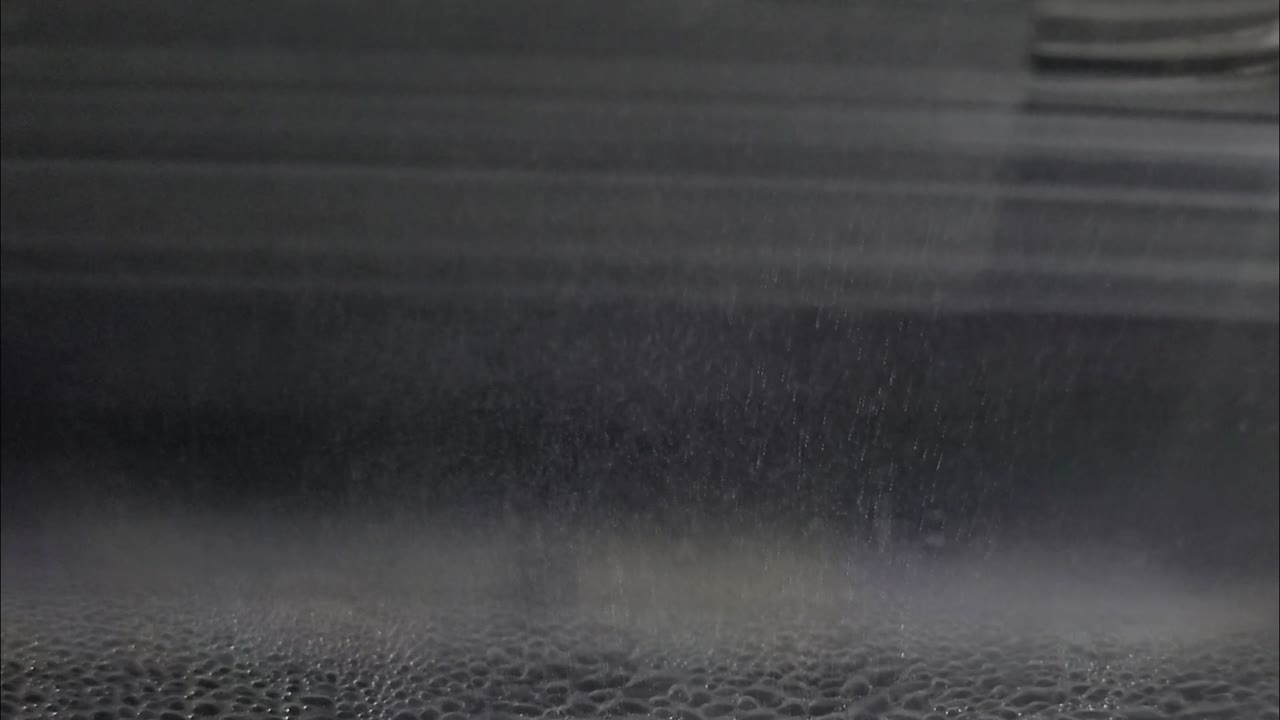
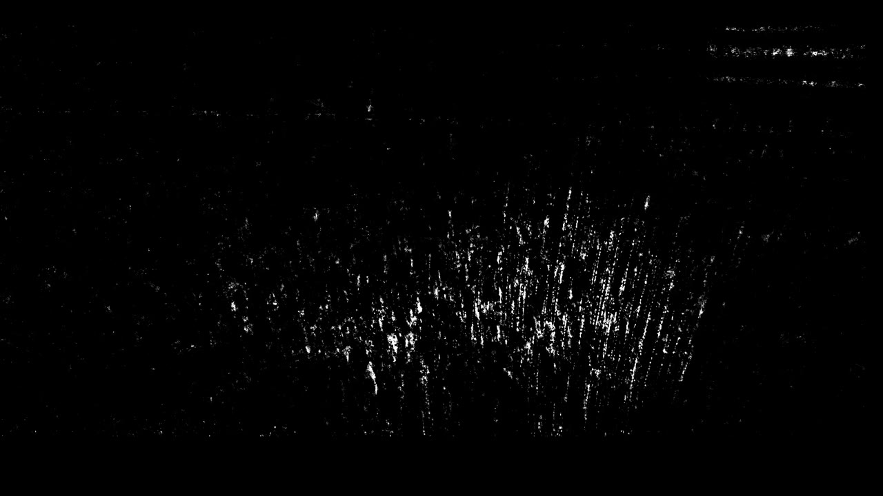
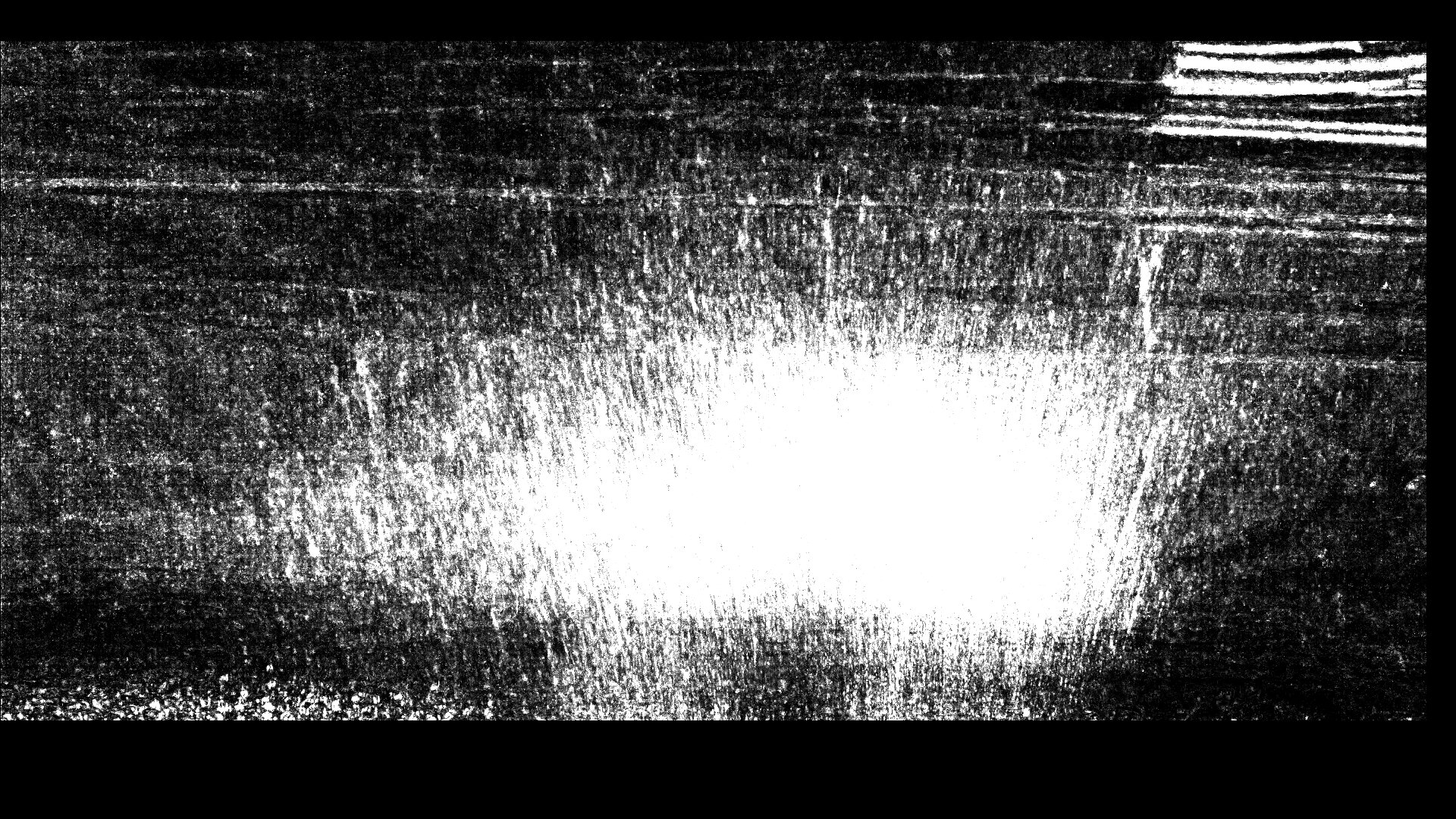
The maximum projection is worth pausing on: it is the closest thing this project has to a photograph of duration. Nothing in it happened simultaneously.
Three actors, and only one of them is in the room. Everything the visitor sees was caused about a second earlier by something they cannot influence, schedule, or hurry.
Entirely outside the installation. Nobody schedules it, nobody in the room affects it, and it has been running for the whole history of the building.
One camera, one browser, three outputs. The gate is deliberately strict — a false flash would be a lie, so the piece would rather miss events than invent them. On real footage it rejects about 32,000 specks for every two tracks it accepts.
The visitor has exactly two inputs: where they stand and how long they stay. Neither changes the rate. Waiting is the interaction.
A single screen showing extracted tracks is a data visualisation. Three surfaces showing the same second from three distances is an argument about evidence: here is the chamber, here is what the machine claims was in it, and here is what is left once it has gone. The visitor can check the middle one against the first, which is the only reason to believe the third.
Trails are the only output with a memory, so they get the only surface with depth. Projected onto hanging mesh rather than a wall, the accumulated tracks sit in the air in front of the wall, cast a softer second image behind themselves, and move when the room does. The two hard surfaces are the present; the cloth is the residue.
The whole signal chain is one camera, one browser and three projectors. There is no server, no render farm and no custom application — the detector that was a Python notebook now runs as a worker inside the page.
The band-pass needs frames on both sides of the one it is judging, so the system is structurally about a second behind the particle. That delay is not hidden or compensated for — it is a real property of the method, and section 06 treats it as the subject rather than a defect.
No idle animation, no ambient shimmer, no attract mode. If there is light on a surface, a particle crossed the chamber. The moment the room lights on anything else, every mark in the piece becomes decorative and the work is over.
Not a shortcut. A projector-driven installation that runs from a served folder has no install, no runtime to version-pin and no compiled binary to lose — and each output is an ordinary window, so alignment is a page, not a hardware problem.
The chamber's field of view is about 150 mm across. The projected image is 2.4 m. That enlargement — roughly 1 : 16 — is the whole spatial proposition: a thing the size of a fingernail, given the size of a person.
Exposure must be locked. Any auto-gain in the camera re-levels the frame between shots and the temporal band-pass reads the change as motion, which produces tracks that were never there.

- An open weave passes most of the light, so the trails land twice — sharp on the mesh, soft on the wall 400 mm behind it. The event acquires depth without any 3D being simulated.
- The visitor can walk behind it. From there the accumulated tracks read in reverse, which is the only place in the room where you are inside the image rather than in front of it.
- It moves. Air from the door, from the projector fans, from a person walking past — the residue of a particle that crossed the room an hour ago drifts slightly because somebody opened a door.
- A little projector blur (the softness control on each screen) stops the pixel grid beating against the weave into a moiré.
The two hard surfaces are the present tense and they are honest but flat: this is the chamber, this is what was extracted from it. The cloth is the only surface carrying time, so it gets the only treatment with a physical dimension.
Read left to right the room is an argument in three moves — cause, evidence, residue — and the visitor can check each one against the one before it. That checkability is what separates this from a screensaver.
A cloud chamber is not a picture of a particle. By the time the droplets are large enough to see, the particle is long gone — it left the box, the table and the building at very nearly the speed of light. What you are looking at is an after-image of a decision the vapour made, a few hundred milliseconds late.
The Timekeeper takes that lateness literally and adds its own to it. The detector needs frames from after the event before it can confirm the event, so it keeps a ring buffer and always judges the middle frame. The room is therefore about a second behind the sky — 22 frames, measured and displayed rather than estimated. Nobody in the room ever sees the present. They see the recent past being confirmed.
All three surfaces share that lag exactly, because all three are drawn from the same judged frame. The visitor cannot catch the room out by looking between them: the surfaces agree with each other, and all of them disagree with now.
Why "timekeeper"
Most of the tracks are muons. A muon is made about 15 km up when a cosmic ray — often a proton thrown out of a supernova or an active galaxy, possibly millions of years ago — strikes the top of the atmosphere. A muon lives about 2.2 microseconds. At that lifetime it should decay roughly 660 m into its journey and never reach the ground at all.
It reaches the ground anyway, because it is moving fast enough that its clock runs slower than ours. Every line in the box is therefore a visible consequence of time being relative: a particle that exists at sea level only because it disagrees with the building about how long the trip took.
The timekeeper of the title is not the installation, and not the visitor. It is the particle. The room is only the dial.
Removing agency, on purpose
Interactive work usually opens by handing the visitor a lever. This piece deliberately does not. There is no button, no proximity trigger, no gesture, and nothing anybody can do to raise the rate. Standing closer does not help. Waving does not help. Waiting does not cause anything either — it just increases the chance you are looking the right way when something happens.
What is left, once the levers are gone, is attention. The piece asks for the one thing a room full of screens has trained out of people: staying still in the dark long enough for something rare to be worth noticing. The reward for that patience is small, brief, and completely real — which is precisely the argument.
The room will mostly be dark
At sea level roughly one muon crosses each square centimetre per minute. Scaled to the chamber's active window and the strictness of the track gate, the honest expectation is a handful of flashes per minute, unevenly spaced, sometimes with a minute of nothing between them.
That emptiness is not a shortfall to be engineered away. A flash every two seconds would be more comfortable and would mean nothing. The rarity is the only thing that makes the event legible as an event.
Build a detector honest enough that the light can only ever mean one thing, then make a room out of it and take the buttons away.
- C.T.R. Wilson's chamber, 1911 — weather apparatus that accidentally became a particle detector.
- The tradition of instruments that are also images.
- Duration pieces that ask for waiting rather than input.
| Stage | Form | Status |
|---|---|---|
| Prototype | Three projections — raw, detect, trails — from one camera and one browser, onto two walls and a hanging mesh cloth | Built and running. Detection validated against Observation #3. |
| Proposed final | Suspended sphere array over a centred plinth, each event lighting the sphere nearest where the track crossed the chamber | Modelled, not built. Depends on the prototype proving the event rate is worth a room. |
The projection prototype is not a mock-up of the sphere room — it is a different answer to the same problem, and it may turn out to be the better one. Projections can show the chamber itself, which spheres cannot; spheres put the event in the visitor's own volume of air, which projections cannot. That choice is still open, and the prototype exists to settle it with evidence rather than taste.
| State | Trigger | What the room does |
|---|---|---|
| Dark | Default | All three surfaces near black. No attract mode. |
| Event | Confirmed track | Appears on raw and detect together; trails takes it and begins an ~8 s decay. |
| Residue | Post-event | Cloth holds the accumulation after both walls have gone dark again. |
| Filling | First ~45 frames | Nothing projected until the ring buffer is full. The room stays honest rather than guessing. |
| Fault | Chamber inactive | Counter shows the last event time. No light. The piece is honest about being down. |
- Projection or spheres for the final. The prototype should answer this — if the measured event rate makes a room of spheres mostly dark and unreadable, the projections win by being able to show the chamber itself.
- Dry-ice duration versus exhibition hours. A Peltier stack removes the daily reload but adds vibration, which the band-pass will read as signal.
- Whether raw and detect should be adjacent (comparable at a glance) or opposite (you must turn around, and cannot hold both at once).
- Whether the counter is shown to visitors at all, or kept for maintenance.
- Cloth scale — 2.0 × 2.5 m reads as an object; a full-width drop would read as a second room.
- Run an eight-hour unattended session on a live camera and get a real event-rate distribution. Everything above depends on that number.
- Re-tune the geometry gate on live camera footage — the current values are measured on Observation #3 at 640 × 360 and are in pixels, so they do not transfer to a different lens or resolution unchanged.
- Build the cloth rig at full scale and test the double image and the moiré against real projector optics.
- Decide projection versus spheres, on the evidence from (1).